AWS NLB and IP Preservation

Network Load Balancers (NLB) are critical in cloud and on-premise network design. NLBs are designed to efficiently distribute network traffic across multiple servers, ensuring that no single server bears too much load, preventing overloading and enhancing the reliability and availability of applications.
Network Load Balancers operate at the transport layer (Layer 4 in the OSI model), routing traffic based on TCP/UDP headers and ensuring efficient traffic distribution without inspecting the payload of the packets.
The AWS Network Load Balancer can handle millions of requests per second, with ultra-low latencies and support for TCP and UDP traffic [1], with rapid scaling in response to traffic changes.
In comparison, its Layer 7 sibling, the Application Load Balancer (ALB) has scaling limitations of being able to double in capacity every 5 minutes. The ALB can be modelled conceptually as each ALB node being an independent EC2 instance [2], with Route53 periodically checking the node's health. If a node fails, the internal load balancing service spins up a new one and updates the ALBs DNS.
In addition to superior scaling abilities, due to the NLB operating at the transport layer, it's capable of something else: transparent Client IP Preservation.
This article discusses Client IP Preservation, legacy techniques and different options for Client IP Preservation when working with the AWS NLB.
Understanding Client IP Preservation
Before diving deeper into an NLB, let's look at techniques for Client IP preservation during load-balancing.
X-Forwarded-For
The X-Forwarded-For header is one of the most common approaches to preserve client addresses, implemented by Layer 7 (L7) HTTP load balancers such as the AWS Classic Load Balancer, AWS Application Load Balancer and HAProxy.
The load balancer first terminates the connection with the client and then makes a new request to the backend, the load balancer adds a header to the request to the backend, containing the original clients IP [3].
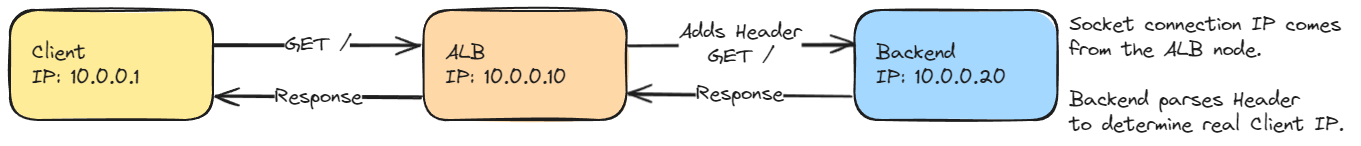
The above flow, might generate HTTP requests at the backend like the following:
GET / HTTP/1.1
Host:myalb-hostname.com
X-Forwarded-For: 10.0.0.1
As a layer 7 load balancer intercepts and terminates the L7 protocol, it can perform additional functionality such as socket reuse to the backends, changing protocols (HTTPS listener / HTTP backend) and changing ports.
Proxy Protocol
The Proxy protocol operates at Layer 4, and is available for AWS Classic and AWS Network Load Balancers [4].
The Proxy protocol was published in October 2010 by Willy Tarreau at HaProxy Technologies [5]; it "provides a convenient way to safely transport connection information such as a client's address across multiple layers of NAT or TCP proxies. It is designed to require little changes to existing components and to limit the performance impact caused by the processing of the transported information" [5].
Version 1 of the protocol is a human-readable ASCII string prepended to the requests TCP data. Version 2 of the protocol is a binary encoding of the header, which is more efficient to produce and parse. Both formats are designed to fit in the smallest TCP segment that any TCP/IP host is required to support and should be delivered and processed in a single atomic action.
The protocol explicitly prevents port sharing between public and private access. If the backend target is configured to accept Proxy Protocol headers, it should only accept Proxy headers. The receiver must ensure proper access filtering is in place so that only trusted proxies can use the protocol [5], otherwise malicious actors could spoof the header.
An example of the V1 protocol can be seen below:
PROXY TCP4 192.168.0.1 192.168.0.11 56324 443\r\n
GET / HTTP/1.1\r\n
Host: 192.168.0.11\r\n
The V2 binary header format starts with a constant 12 bytes block containing the
protocol signature and can be seen by inspecting the TCP data stream.
\x0D \x0A \x0D \x0A \x00 \x0D \x0A \x51 \x55 \x49 \x54 \x0A
In both cases, the protocol places an easily parsable header placed by the proxy at the beginning of each connection. However, the backend targets must be aware that the header is expected. As a result, it requires additional backend server configuration over alternative methods shown here.
Direct Server Return (DSR)
Direct Server Return is a load-balancing technique where each backend server is configured with a virtual service IP (VIP) on its loopback interface. A load balancer in front of the servers is responsible for changing the destination MAC address of the packets, and the backends answer directly to the client using the service IP configured on the loopback interface.
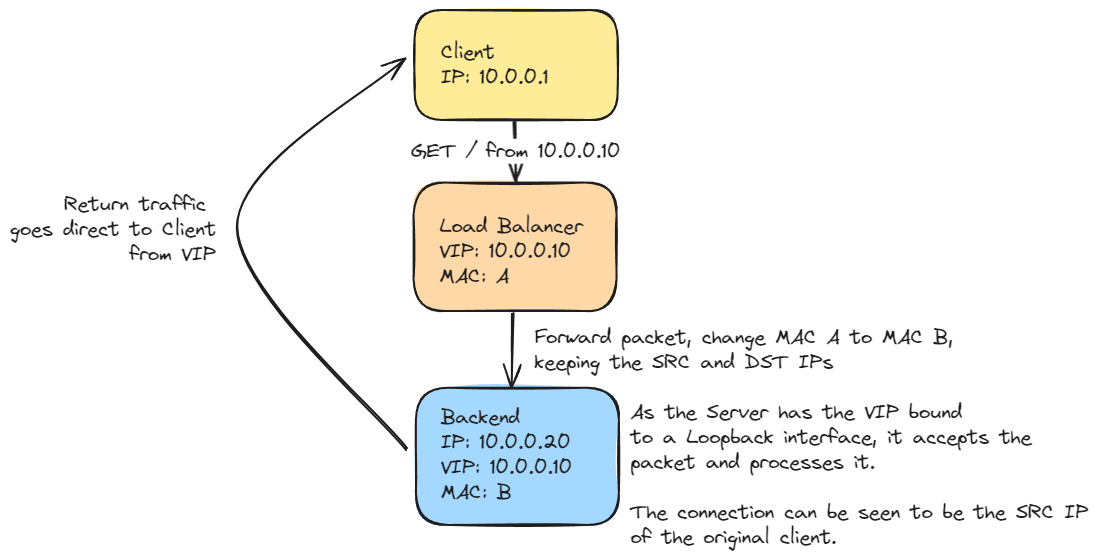
This technique results in high-speed load balancing, where the output bandwidth is the sum of all backend nodes. However, it has some complexities, such as configuring a shared service IP on each backend. It also requires dedicated load-balancing hardware, and the implementation typically needs to be aware of any issues arising from asymmetric traffic flows.
BGP Load Balancing
Border Gateway Protocol (BGP) is a critical technology in the internet and is used for determining how data packets should be routed between routers.
Combined with Equal Cost Multi-Pathing (ECMP), BGP and ECMP can be utilized for efficient and reliable load balancing at a large scale, often in the data centre and enterprise network environments, by utilising redundant routers as large-scale layer four load balancers.
BGP load balancing is a growing trend at hyper-scale and is used by large workloads such as Facebook's Global Load Balancer and Google's Maglev network load balancer.
Similar to Direct Server Return, multiple servers can be serving the same IP (known as AnyCast); it is then the responsibility of BGP-enabled routers to direct traffic flows to backend hosts, using consistent flow tuple hashing to ensure the same stream of data is sent to the same backend server [6].
Typically, this is implemented with the host advertising via BGP that it is ready to serve an IP address or IP range using Linux software such as exaBGP [10]. The router then registers this as a next-hop and sends traffic to it, resulting in the client communicating directly with the backend server, with the router directing the traffic flow accordingly.
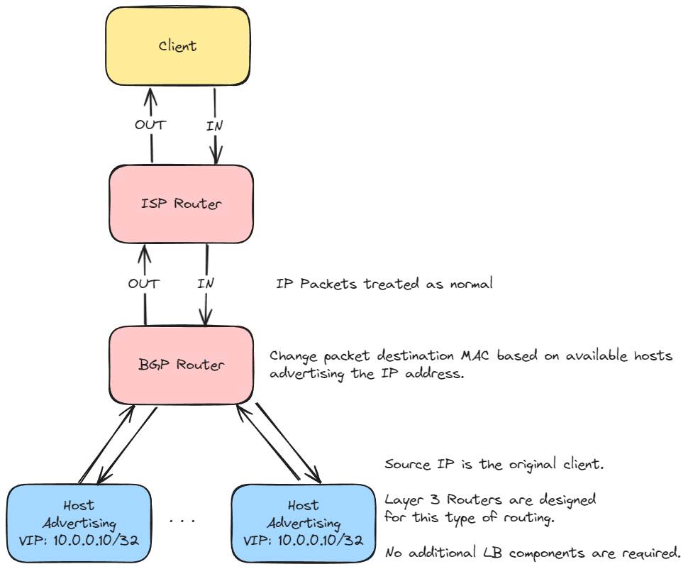
This approach removes the reliance on load balancer hardware, relying on the standard network routers to load balance traffic. When using AnyCast exposed to the internet, the approach can be used for global load balancing, ensuring a client connects to the closest (by network hops) datacenter.
Summary
The approaches highlighted show some common techniques of exposing the client IP to the backend server node and are ordered in terms of scalability, with the layer 7 load balancers requiring dedicated compute, all the way to a BGP setup, where routers act as layer 3 network load balancers without additional dedicated components.
How does an AWS NLB work?
We've seen some approaches to load balancing and client IP preservation commonly used in on-premise infrastructure. However, how does an AWS NLB work at scale, allowing scaling to millions of requests per second without any significant ramp-up duration?
Under the hood, AWS NLB runs on the AWS HyperPlane infrastructure, an internal service publicly introduced at AWS re:Invent 2017 and has been in production since 2015 [7].
AWS HyperPlane is a distributed packet forwarding system running on EC2 instances [8] deployed in each availability zone within a region. The system is multi-tenant (customers share the compute) and utilises shuffle sharding of the nodes (see builders library for more information) to help prevent noisy neighbour performance impacts.
HyperPlane is used by several services where high-performance state tracking is important, including Elastic File System, AppRunner, Managed NAT, Private Link, Transit Gateway [9] and Gateway Load Balancer [2]. The technology solves a distributed consensus problem, ensuring network ports for specific IPs are unique for use in a transactional robust manner.
In the case of an NLB, this involves tracking the state of an inbound TCP/UDP connection to a specific backend target. A single NLB/HyperPlane ENI runs on a subset of HyperPlane nodes within an AZ. Each participating HyperPlane node knows about all transactions of other nodes and can safely route packets to the target, allowing the system to scale beyond a single machine.
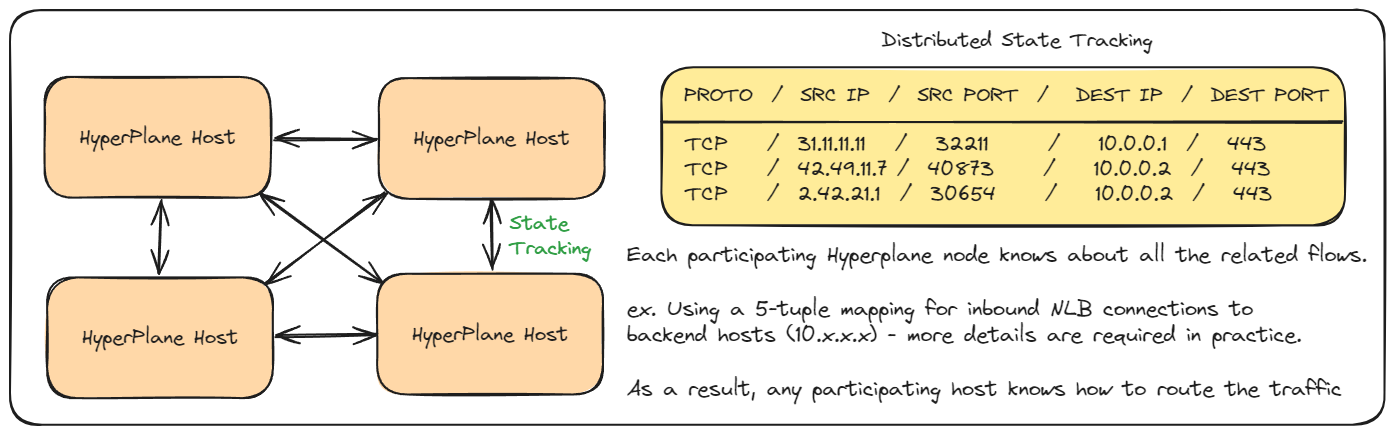
This allows the network load balancer (1 IP address per availability zone) to scale beyond a single machine (as with Application and Classic Load Balancers).
The underlying VPC network randomly delivers packets inbound to a network load balancer to a participating HyperPlane host. Check out the great talk by Colm MacCárthaigh AWS reInvent 2017: Another Day, Another Billion Flows, for more information.
NLB Client IP Preservation
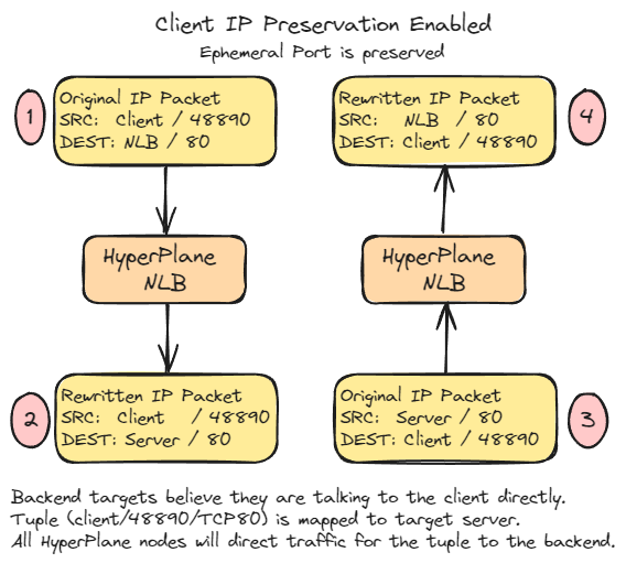
By default, IP Preservation with an NLB will make it look like the packet has come directly from a client; that is, the NLB is transparent. In the following diagram, we can observe TCP packets seen by both the client and the server when Client IP Preservation is enabled.
- The client sends the packet to the NLB IP address (resolved via DNS).
- The NLB rewrites the Destination IP of the packet and forwards it to the server. A tuple is stored in the distributed state, mapping the client connection to the server.
- The server replies to the client, but the NLB intercepts the flow.
- The NLB rewrites the Source IP of the packet and forwards it to the client.
The following results are from a real-world tcpdump using an NLB and Client IP Preservation.
| Seq/Ack | Client (172.31.15.152) |
NLB (172.31.4.97) |
Server (172.31.7.180) |
|---|---|---|---|
| seq 1:127 ack 1 |
172.31.15.152:48890 > 172.31.4.97:80 | > | 172.31.15.152:48890 > 172.31.7.180:80 |
| seq 1:10983 ack 127 |
172.31.4.97:80 > 172.31.15.152:48890 | < | 172.31.7.180:80 > 172.31.15.152:48890 |
Client IP Preservation and self-calling
It's worth noting that this IP preservation behaviour can have interesting side effects if a server calls an NLB, which routes traffic back to the same server. When using the NLB with Kubernetes environments with complex routing requirements, this is worth considering.
In this scenario, the operating system sees a packet where the SRC Address is itself, which causes the operating system to drop the packet immediately. This will result in the socket timing out.
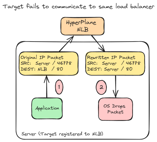
The following snippet is from a tcpdump attempting this flow. It can be seen the written packet has an SRC of the host itself; the packet is dropped, and no further packets are seen.
Server: 172.31.23.138
NLB: 172.31.22.112
Outbound: 172.31.23.138:46778 > 172.31.22.112:80: seq 355106775
Inbound: 172.31.23.138:46778 > 172.31.23.138:80: seq 355106775
This behaviour is documented on AWS re:Post. There are two possible workarounds:
- Disable Client IP Preservation
- Disable Client IP Preservation and use Proxy Protocol V2
Client IP Preservation Disabled
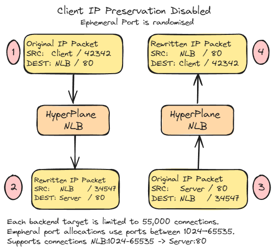
With Client IP Preservation Disabled, the behaviour of an NLB differs, and each backend target is limited to 55,000 connections. This is due to the ephemeral port allocations used between 1024-65535, so only NLBIP:1024-65535 -> Backend:80 can be supported concurrently.
- The client sends the packet to the NLB IP address.
- The NLB rewrites the packet, changing the SRC IP, SRC Port and DEST IP, and the packet is delivered to the server. A tuple is stored in the distributed state, mapping the client connection to the server.
- The server responds to the NLB IP and NLB ephemeral port.
- The NLB rewrites the packet's destination to the original Client IP and Port.
| Seq/Ack | Client (172.31.15.152) |
NLB (172.31.4.97) |
Server (172.31.7.180) |
|---|---|---|---|
| seq 1:127 ack 1 |
172.31.15.152:42342 > 172.31.4.97:80 | > | 172.31.4.97:34547 > 172.31.7.180:80 |
| seq 1:10983 ack 127 |
172.31.4.97:80 > 172.31.15.152:42342 | < | 172.31.7.180:80 > 172.31.4.97:34547 |
In this mode, the NLB can be modelled as an almost reverse NAT, performing address and port translation for every packet in the flow. It exhibits the same 55,000 connection limit per IP as the AWS NAT Gateway [11].
NLB Proxy Protocol V2
The NLB supports the Proxy Protocol V2, which prepends the Proxy header to the initial connection setup phase within the TCP data.
The following image shows the raw hex of a Proxy Protocol header, prepended into a TCP stream by the Network Load Balancer. Applications must be expecting this additional data.
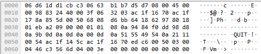
Below we can see what an ASCII representation of the TCP data looks like, with the Proxy Protocol V2 header, just before the ASCII GET command.
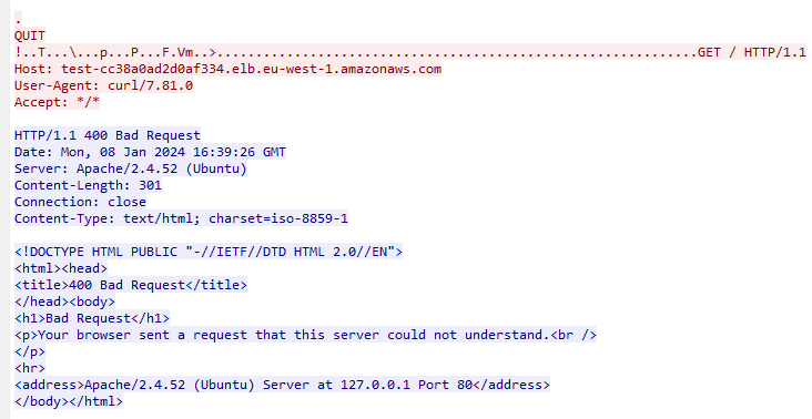
The Apache2 server must be configured to understand the header. It's important to remember that the Proxy V2 Protocol is L7 protocol agnostic; that is, the NLB will inject the same header at the start of every TCP stream, regardless of the application level protocol (ex. SSH / HTTP / HTTPS / FTP).
In this example, Apache has returned a 400 Bad Request when Proxy V2 is enabled. This is because backend software must be explicitly configured to accept and use the proxy protocol.
The following guides highlight how to enable it for various server software:
Summary
This article discusses legacy load-balancing techniques that share the same fundamentals as modern cloud load balancers.
AWS NLBs demonstrate high throughput using distributed flow tracking and mutate packets before delivery to a backend target host. The AWS NLB has various options to preserve the client's original IP address, including preserving the IP within the packet (L3/L4) or using Proxy Protocol V2 to prepend the data to the client TCP data.
Depending on which option is chosen, there are various technical limitations; for example, if you have client IP preservation disabled, the number of connections to each backend target is limited to 55,000.
If you wish to use Proxy V2, additional configuration steps must be made on the backend to understand the request. As such, standard IP Preservation is the desired option when possible, allowing for seamless and fully transparent routing to backend hosts.
References
- AWS - Network Load Balancers
- YouTube - AWS re:Invent 2022 - Building resilient networks
- Mozilla - X-Forwarded-For
- Kevin Hakanson - AWS LB Support
- HAProxy - Proxy Protocol Specification
- Cisco - ECMP Load Balancing
- AWS PrivateLink Presentation
- AWS re:Invent 2017: Another Day, Another Billion Flows (NET405)
- Aviatrix - AWS Transit Gateway
- ExaBGP
- AWS VPC NAT Gateway